Heatsink Design-ZZcooler Electronics Company
General Rules for Heat Sink Design
Drive the heat from the component to air within the available volume and temperature difference
Thermal interface material at contacting surfaces
Area and conductivity for conduction and spreading
Surface area for convection and radiation
Surface treatment for convection and radiation
At a minimum in raw material cost
Least volume / mass of material
Lowest cost material
At a minimum in manufacturing process cost
Material compatible with versatile, low cost, low waste processes
Easy to prototype, cost effective to mass produce
With robust mechanical retention, easy installation
Heat Sink Design Methods
Heat transfer correlations
Quick back of the envelope calculations
Rough size of heat sink required
Numerical Design Tools ¨C QFIN
Combine correlations with numerical conduction calculations
More robust handling of geometry details, flow bypass, interfaces, ducts, fans ˇ
Comprehensive Design Tools
Icepak CFD software ¨C interface tailored for electronics cooling
Gambit + Fluent CFD software ¨C full capability tools
Selection Criteria & Metrics
Heat Transfer Performance: W/oC/Volume
Fin density required
Type of spreading required
Weight & Cost:
mass/Volume, mass/W;
cost/volume, cost/W
Form factor & shape
Fin aspect ratios ¨C type of fin technology
Distance for heat transport in the x, y, and z directions
Spreading enhancement
Need heat pipes?
How many?
Heat Sink Application Inputs
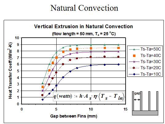
Natural convection
Given heat sink temperature delta above air & length of flow path
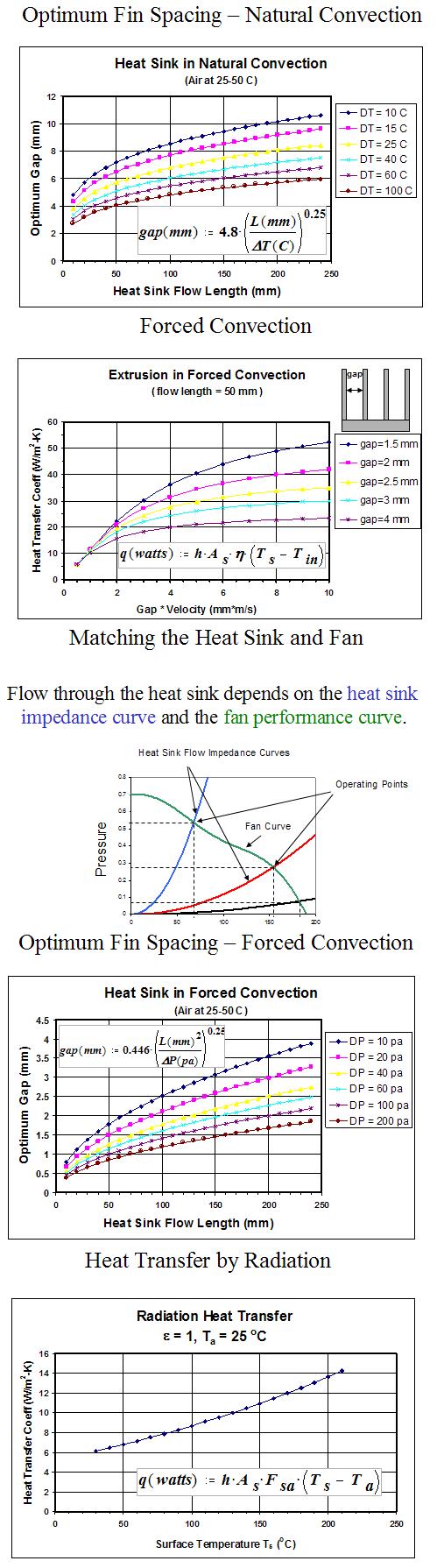
Forced convection
Ducted air flow without bypass
Given fan curve ¨C use limits 0.7*CFM_max & 0.4*P_max
Given max flow and pressure ¨C use pressure for design then check if CFM is within limits
Non-ducted air flow with significant bypass
Use 1.3X dynamic head of approach flow as driving pressure
(will need to solve flow bypass network for final design)
Fan-heat sink
Use 0.5*CFM_max and 0.5*P_max
Mass limits (x,y,z are dimensions in meters)
mass < x*y*((z-0.006)*0.25+0.006)*2700 (kg) ¨C extrusion possible
Otherwise will likely need assembled fin technology heat sink
Fin Density Required
x-y is plane of heat sink base, z is normal to base
Check thermal performance requirement
Separate spreading resistance to get ~fin resistance required
Spreading ¨C from heat source over x-y size & base thickness (Seri Lee Formula)
W/oC/cu. in. of Fin Volume ¨C select fin density (Al Fins)
Below 0.03 ¨C Natural Convection possible
Below 0.20 ¨C Low Density Fins, Low DP (gaps >~ 3 mm)
Below 0.40 ¨C High Density Fins, Low DP (<~20 Pa)
Below 0.65 ¨C High Density Fins, High DP (Blowers)
Above 0.80 ¨C Look for liquid or two-phase radiator type HS
If getting close to each limit, consider next higher option or copper
The above performance limits increase by 15% if weight limits allow copper fins.